
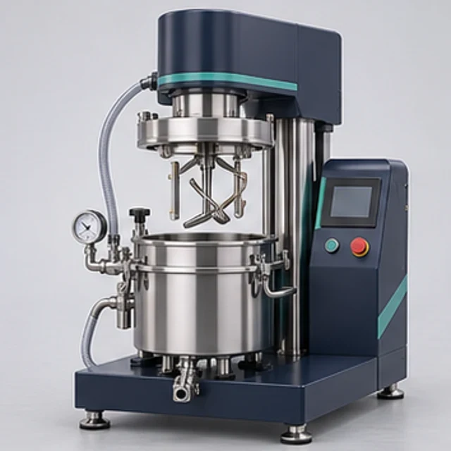
 REPRESENTATIVE CONCEPT
Under Development
Laboratory Vacuum Planetary Mixer
Li-ion Laboratory EquipmentLaboratory slurry mixing under controlled pressure.
AMB-LPM-05Explore equipment ↗
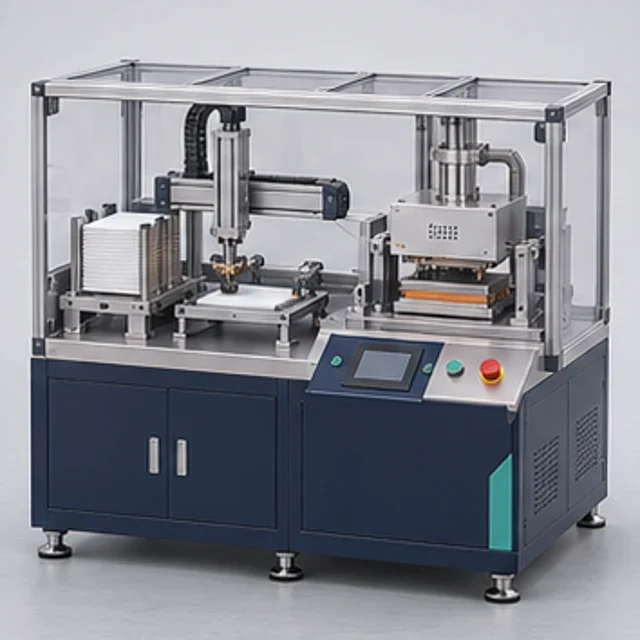
Intended for developing the circumferential groove in compatible cylindrical cell cans, with can support and component clearances established from the selected cell design.
| Technical Parameter | Indicative Configuration |
|---|---|
| Equipment type | Laboratory cylindrical cell-can groove rolling machine |
| Operating principle | Controlled local forming with supported can and shaped roller |
| Proposed configurations | 18650 / 21700 / custom can tooling |
| Cell format | Each can format requires dedicated validated tooling |
| Can material | Selected steel or aluminium cases, subject to forming trials |
| Can wall thickness | Can-drawing and material-dependent |
| Groove location | Adjustable stop/fixture; defined from cap and seal design |
| Groove width | Selected roller profile; not a universal dimensional rating |
| Groove depth | Mechanically adjustable; validated against can wall and internal clearances |
| Forming motion | Driven can/tool rotation with controlled roller approach |
| Rotation speed | Variable, established during forming trials |
| Roller tooling | Replaceable hardened tool-steel forming roller |
| Can support | Matched support/mandrel arrangement where assembly permits |
| Loading | Manual loading and unloading |
| Actuation | Mechanical setting with pneumatic approach, selected configuration |
| Pneumatic supply | Proposed 5–7 bar for pneumatic version; final circuit-dependent |
| Drive | Geared motor with electronic speed control |
| Control system | Simple sequence controls; PLC/HMI optional for custom integration |
| Setting adjustment | Groove location and approach set independently for selected tooling |
| Part inspection | External dimensional checks and can-damage inspection |
| Debris control | Controlled tooling cleanliness and removable collection arrangement |
| Frame construction | Fabricated/machined steel with rigid tooling support |
| Electrical supply | 230 V AC proposed; final motor and controls to be selected |
| Safety | Rotating-zone guarding, interlocks and controlled approach/return |
| Downstream interface | Separate cap/sealing operation after groove validation |
| Application | Cylindrical cell-can groove development and laboratory assembly trials |
Technical specifications are indicative and configurable. Final equipment parameters, performance, compatibility and supply arrangements will be confirmed following application review and engineering evaluation.
| Model | Principal Capacity / Range | Configuration | Intended Application |
|---|---|---|---|
| AMB-CGR-18650 | 18650 can-format tooling proposal | Manual loading; driven groove forming | Laboratory 18650 can-groove development |
| AMB-CGR-21700 | 21700 can-format tooling proposal | Dedicated support and roller set | Laboratory 21700 assembly trials |
| AMB-CGR-C | Customer can drawing and material | Custom support and groove tooling | Other can formats subject to feasibility |
The model labels identify proposed can-tooling configurations, not proven format compatibility or available stock. Groove width, depth, force, rotational speed and capacity require can drawings and forming trials. No production rate, dimensional accuracy, tool life or cap-sealing performance is established. Independent tooling/mechanism design is required; competitor construction is not a design template.
Configurable laboratory equipment is engineered around customer-specific process and capacity requirements. A shaped forming roller and matched can support develop a circumferential groove at the location defined by the can closure design. Proposed manually loaded configurations use simple mechanical settings, a controlled approach and driven rotation. Groove geometry and internal clearances require development with representative cans.
Cylindrical cell assembly trials and development of can-groove tooling for a defined case design. Confirm the intended process, materials and acceptance method during application review.
Mechanical interfaces, operating mode and control requirements are defined during engineering review. Available configuration choices depend on the agreed equipment scope.
Simple controls and variable-speed drive are proposed; PLC/HMI and automated handling are optional custom developments.
Final equipment selection, utilities, site interfaces and supply feasibility are established during application review. This enquiry-led listing does not establish current stock, completed manufacture or testing, dispatch availability, or an appointed specialist supplier.
Can wall strain, roller load, internal jelly-roll/insulator clearances, can support, groove inspection and the downstream seal interface require validation. Rotating and forming pinch points need suitable guarding and interlocked access. Pneumatic isolation, pressure limits and controlled return require design review. No cell safety, forming tolerance, patent clearance or tooling durability is established.
A documented risk assessment, guarding review, material compatibility check and application-specific operating procedure are required before use. No CE, UL, IEC, hazardous-area approval or other certification is established by this listing. Conformity documentation depends on the agreed scope and destination requirements.
Read the Product Information Disclaimer
Request technical documentation and an application-specific configuration with your enquiry.
This listing represents an intended equipment or engineering offering. Feasibility, configuration and availability require confirmation. Please request the current engineering and supply status.
Share your materials, required capacity, process constraints and acceptance criteria. The team will review feasibility before confirming any custom scope.
REPRESENTATIVE CONCEPTLaboratory slurry mixing under controlled pressure.
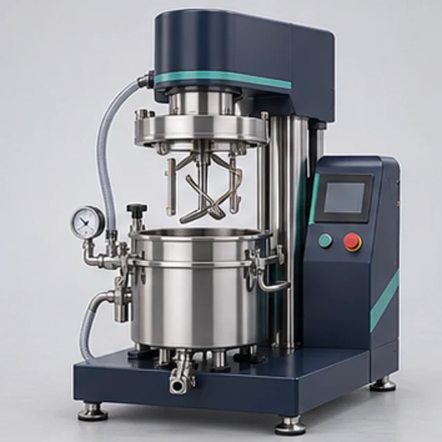 REPRESENTATIVE CONCEPT
Laboratory rotor-stator dispersion.
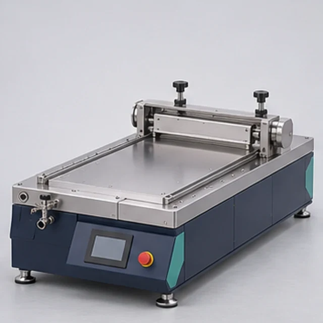 REPRESENTATIVE CONCEPT
Laboratory blade coating of electrode coupons.