
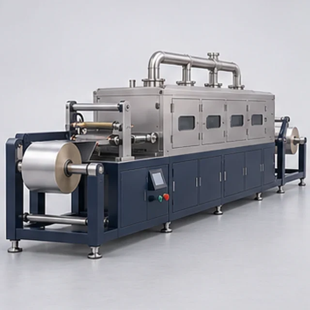
 REPRESENTATIVE CONCEPT
Planned
Battery Module Assembly Station / Line
Module AssemblyBattery module assembly workflow.
AMB-MAS-10Explore equipment ↗
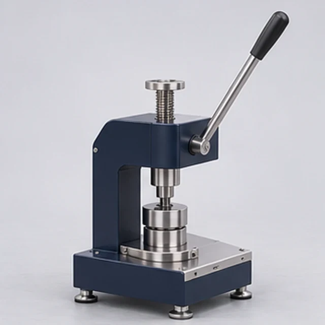
Intended for controlled positioning or compression of a selected cell stack during module assembly, with allowable cell loading defined by the cell and module design owners.
| Technical Parameter | Indicative Configuration |
|---|---|
| Module size envelope | Application-specific module envelope (mm) |
| Cell/module arrangement | Cell/module arrangement per customer drawings |
| Compression axis | Selected single-axis compression direction |
| Maximum opening and working stroke | Opening and stroke (mm) determined from loading and fixture geometry |
| Compression force range | Design-dependent force (N/kN); limited by customer cell specification |
| Force adjustment | Mechanical setting or regulated/controlled actuation, selected design |
| Actuation method | Manual / pneumatic / hydraulic; servo option only where justified |
| Frame construction | Rigid fabricated/machined frame sized for agreed loads |
| Platen dimensions | Application-specific platen area (mm) |
| Platen parallelism verification | Inspection under agreed load and measurement method; no tolerance claimed |
| Guide mechanism | Guided ram/platen arrangement suited to selected load |
| Contact tooling | Replaceable load-spreading tooling |
| Electrical insulation | Selected insulating interfaces to protect live cell components |
| Force sensor option | Optional calibrated load cell |
| Position sensor option | Optional position transducer |
| Displacement monitoring | Optional displacement monitoring with selected sensor |
| Hold-time setting | Application-specific mechanical hold or programmed hold if powered |
| Fixture changeover | Replaceable tooling with controlled setup checks |
| Positioning stops | Adjustable locating stops and module restraints |
| Control arrangement | Manual standard; suitable powered sequence control where selected |
| Optional data logging | Optional force/position record for selected monitored version |
| Pneumatic/hydraulic utilities | Selected circuit pressure/flow; hydraulic pack where required |
| Electrical supply | None for purely manual fixture; selected powered-system supply |
| Guarding and anti-crush safeguards | Guarded crush zone, controlled approach/release and assessed access |
| Customer-defined allowable cell loads | Allowable force, compression and damage criteria supplied by cell/module design authority |
Technical specifications are indicative and configurable. Final equipment parameters, performance and supply arrangements will be confirmed following application review and engineering evaluation.
Force and stroke are engineered from the customer cell/module limits, not inferred from the product ID. Manual and pneumatic concepts do not automatically include servo control, sensors or data logging. No validated compression outcome is established.
Configurable engineering solutions are developed around customer-specific process and capacity requirements. The proposed solution families are Manual controlled-compression fixture; Pneumatic module compression press; Hydraulic or servo-controlled press; optional force monitoring. Configuration, acceptance and supply feasibility are established for the enquiry; this listing does not establish completed models or current stock.
Module-fixture development, stack build-up studies and controlled assembly before retention hardware is fixed. Confirm the intended process, materials and acceptance method during application review.
Mechanical interfaces, operating mode and control requirements are defined during engineering review. Available configuration choices depend on the agreed equipment scope.
Force and stroke are engineered from the customer cell/module limits, not inferred from the product ID. Manual and pneumatic concepts do not automatically include servo control, sensors or data logging. No validated compression outcome is established.
Manual fixtures use no powered control unless selected. Electrical and pneumatic/hydraulic utilities are defined only for the chosen configuration; site interfaces are confirmed during technical review. No unselected servo, PLC, HMI or specialist module is automatically included.
Force distribution; cell damage. Force and stroke are engineered from the customer cell/module limits, not inferred from the product ID. Manual and pneumatic concepts do not automatically include servo control, sensors or data logging. No validated compression outcome is established. Application-specific risk assessment, safeguards and acceptance validation are required before operation.
A documented risk assessment, guarding review, material compatibility check and application-specific operating procedure are required before use. No CE, UL, IEC, hazardous-area approval or other certification is established by this listing. Conformity documentation depends on the agreed scope and destination requirements.
Read the Product Information Disclaimer
Request technical documentation and an application-specific configuration with your enquiry.
This listing represents an intended equipment or engineering offering. Feasibility, configuration and availability require confirmation. Please request the current engineering and supply status.
Share your materials, required capacity, process constraints and acceptance criteria. The team will review feasibility before confirming any custom scope.
REPRESENTATIVE CONCEPTBattery module assembly workflow.
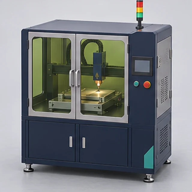 REPRESENTATIVE CONCEPT
Module busbar laser joining.
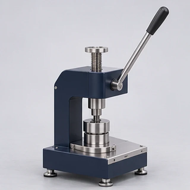 REPRESENTATIVE CONCEPT
Coin-cell case crimping.