
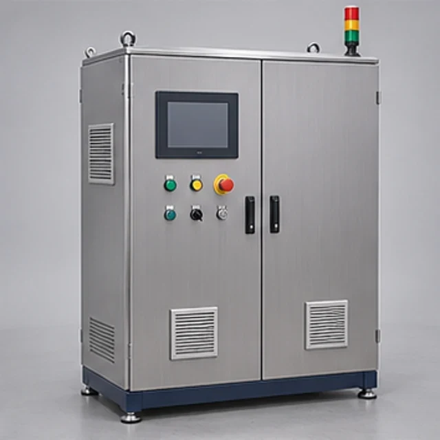
 REPRESENTATIVE CONCEPT
Planned
BMS Installation & Flashing Station
Pack AssemblyBMS installation and software loading.
AMB-BMS-01Explore equipment ↗
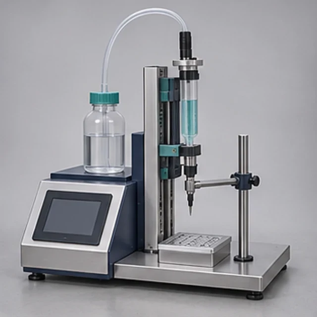
Intended for applying a controlled bead or pattern of compatible thermal-interface material within a module or pack, with wet-out and final bond-line conditions determined by the design.
| Technical Parameter | Indicative Configuration |
|---|---|
| Equipment type and application | Application-specific TIM dispensing for module/pack thermal interfaces |
| TIM chemistry and component count | Customer-selected paste/gap filler; chemistry and component count confirmed |
| Pack/module substrate dimensions | Application-specific substrate envelope (mm) |
| Dispensing method | Selected volumetric/pressure dispensing with material-compatible tooling |
| Single-component or two-component system | Single-component or separately selected meter-mix system |
| Mix-ratio selection, where applicable | Material-specified ratio; achieved ratio requires selected-system evidence and trials |
| Material viscosity compatibility | Pump, hoses and nozzle selected from actual material rheology and temperature |
| Metering principle | Selected piston, progressive-cavity or suitable specialist metering principle |
| Dispensing volume per shot | Application-specific mL/shot or g/shot; no universal accuracy claim |
| Dispensing flow rate | Selected material/system flow (mL/min or g/min) confirmed by trials |
| Bead width/height or pattern | Joint-defined bead dimensions (mm) or coverage pattern; validated on actual parts |
| Dispensing nozzle | Selected compatible nozzle/mixer and shutoff arrangement |
| Metering pump arrangement | Specialist pump/meter-mix components matched to abrasive/filler properties |
| Material reservoir/cartridge | Compatible cartridge, pail or bulk supply selected for material |
| XYZ/robot positioning | Manual presentation; programmable XYZ or robot option |
| Axis travel, application-specific | Application-specific travel (mm) per fixture/path |
| Motion control architecture | Simple controller where sufficient; multi-axis integration only where selected |
| Material temperature conditioning, optional | Optional conditioning subject to material supplier limits |
| Pot life and purge provisions | Material-defined pot life; replaceable mixers and controlled purge/waste handling |
| Part positioning fixture | Custom datum-based support and clamping |
| Optional weighing/vision verification | Optional dose weighing/bead vision, validated for acceptance method |
| Recipe storage and traceability | Optional controlled recipes and part/material/result association |
| Electrical/pneumatic requirements | Selected component power and air requirements confirmed at design |
| Chemical/pressure/operator safety | Pressure isolation, guarded motion, chemical exposure and safe purge controls |
| Changeover and cleaning | Material-compatible flushing/replacement and controlled contamination/changeover |
Technical specifications indicate configurable equipment solutions. Final capabilities, operating parameters, instrumentation, performance and supply arrangements will be confirmed following application review and detailed engineering.
Specialist meter-mix components are selected for the actual TIM. Mix ratio, dose accuracy, flow, bead geometry and throughput need component evidence and material trials. Single-component, two-component and automated positioning are separate scope choices; material conditioning and verification are optional.
Application-specific solutions combine mechanical engineering and automation integration with selected specialist subsystems. Proposed configurations include Single-component paste/gap-filler dispensing; Two-component metering and mixing; Programmable XYZ or robot-integrated dispensing. Only the explicitly selected configuration and operations form the agreed scope. This enquiry-led listing does not establish completed manufacture, installations, inventory or a confirmed supplier appointment.
Pack cooling-plate assembly, module thermal-interface trials and controlled placement of paste or gap-filler materials. Confirm the intended process, materials and acceptance method during application review.
Mechanical interfaces, operating mode and control requirements are defined during engineering review. Available configuration choices depend on the agreed equipment scope.
Specialist meter-mix components are selected for the actual TIM. Mix ratio, dose accuracy, flow, bead geometry and throughput need component evidence and material trials. Single-component, two-component and automated positioning are separate scope choices; material conditioning and verification are optional.
Electrical, communication and any compressed-air/conditioning requirements follow the actual selected components and site interfaces. Basic manual fixtures do not automatically include PLCs, servo drives or HMI systems. Utilities, optional modules and integration responsibilities are confirmed in the technical scope.
Material handling; consistency. Specialist meter-mix components are selected for the actual TIM. Mix ratio, dose accuracy, flow, bead geometry and throughput need component evidence and material trials. Single-component, two-component and automated positioning are separate scope choices; material conditioning and verification are optional. Customer-approved acceptance, application-specific risk assessment and appropriate safeguards are required before operation or substitution.
A documented risk assessment, guarding review, material compatibility check and application-specific operating procedure are required before use. No CE, UL, IEC, hazardous-area approval or other certification is established by this listing. Conformity documentation depends on the agreed scope and destination requirements.
Read the Product Information Disclaimer
Request technical documentation and an application-specific configuration with your enquiry.
This listing represents an intended equipment or engineering offering. Feasibility, configuration and availability require confirmation. Please request the current engineering and supply status.
Share your materials, required capacity, process constraints and acceptance criteria. The team will review feasibility before confirming any custom scope.
REPRESENTATIVE CONCEPTBMS installation and software loading.
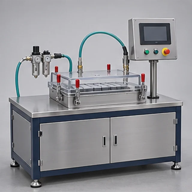 REPRESENTATIVE CONCEPT
Pack cooling-circuit assembly and leak checks.
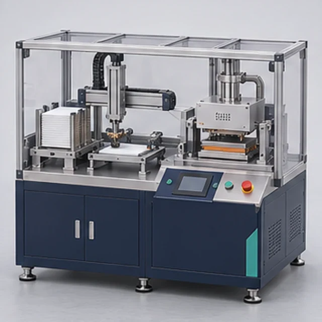 REPRESENTATIVE CONCEPT
Pack enclosure gasket and seal assembly.